| >next> Foto Documentation August 2015 |
Understanding Morandi - The Post-Stressed Conrete Cable Stays
|
I would be grateful for comments, please scroll down to the page footer
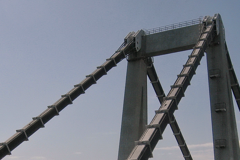
Riccardo Morandi, the lead engineer of the Polcevera Viaduct, was one of the few engineers to employ concrete-encased, post-tensioned stay cables in bridges. This made me curious about the reasons for this choice and about how the system works. First, a look at Pylon 9:
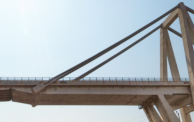 |
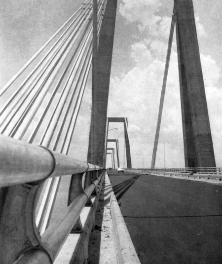
| Image 1 (Hasenjäger 2015): Pylon 9 - The stay consists of two distinct lower stay members, which merge halfway up towards the tower. |
Let us consider two cross-sections of these stays. Note the two kinds of cable bundles: type A and type B. The 24 inner type-A bundles consist of 12 parallel independent cables each, while the 28 outer type-B bundles consist of 4 parallel independent cables each.
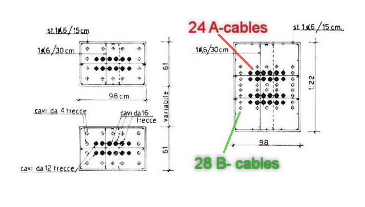 |
| Image 2 (Morandi 1968): Two stay cross-sections. 24 type-A bundles of 12 cables each and 28 type-B bundles of 4 cables each. |
In the drawing above, the right cross-section is located somewhere in the upper part of the stay, towards the top of the pylon. The cross-section to the left is located in the lower part. In fact, there are two superimposed stay packages that merge further up, adding complexity to the structural system, especially over the long term.
Also note that the cross-section drawings show cables of two different diameters: thicker A-cables and thinner B-cables. They have very different structural functions and installation procedures:
The primary A-cables were first installed and tensioned, supporting the weight of the box-girder cantilever deck at their ends. At this stage, there was still no concrete encasement around them. Therefore, no precise prestressing of the concrete member was possible yet. This was done in a subsequent step with the B-cables, as explained below.
The photo below shows this construction phase: two sets of 12 inner A-cables have been tensioned, still without the concrete encasement around them, but already supporting the cantilever deck.
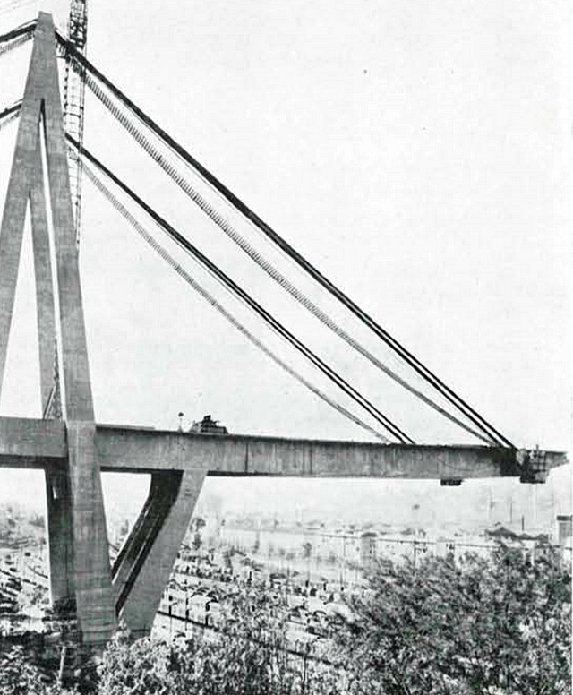 |
| Image 3 (Morandi 1968): Twenty-four bundles of bare A-cables supporting part of the cantilever deck, prior to concrete casting. |
In a subsequent construction step, a concrete encasement was cast in formwork supported by the inner type-A cable bundles. Image 4 below most likely shows a more advanced version of such a process during construction of the Carpineto Viaduct around 1977. As the image below shows, attached precast concrete shell elements or formwork units were used. In Genoa, the stays were most likely cast in situ using external formwork (to be confirmed).
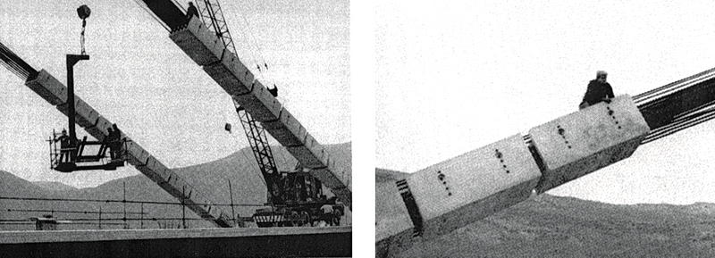 |
| Image 4 (Sala 2016): Precast concrete shell elements are being attached to the main A-cables of the Carpineto Viaduct around 1977. The elements would later be filled with concrete and then post-tensioned with additional B-cables. |
The 28 outer type-B cable bundles were inserted once the concrete stay beam was largely completed, as the image below shows. Note that the (green) type-B bundles are not yet tensioned (loose ends), while the (red) type-A bundles support the weight of the bridge deck.
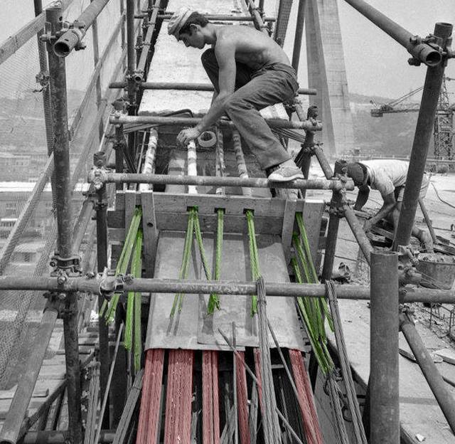 |
| Image 5 (unknown source): A worker winds tape around a sheath through which a type-B bundle (four cables each, colourized in green) is routed. At this point, these type-B bundles are neither tensioned nor connected to the bridge structure yet. Separated by a steel sheet, a layer of six type-A bundles (colourized in red) is already tensioned and fully supports the bridge deck. The void inside the sheaths was later filled with cement grout. However, it appears that this process was not carried out with sufficient care, leaving voids or cavities at some points. Note the guardrail on the far right, whose presence indicates that tensioning of the B-cables took place once the bridge's final dead load had mostly been reached. |
The outer B-cables were mechanically post-tensioned to keep the concrete stay beam under constant longitudinal compression. In fact, Morandi thought that applying higher tension to the outer B-cables and lower tension to the inner A-cables would reduce fatigue and wear in the "main" A-cables. The prestressing force applied to the outer B-cables had to be high enough for the stay to sustain the maximum service load, including road traffic. Remember that only the tension in the outer B-cables could be precisely calibrated during construction.
However, a major problem arose: after the concrete encasement around the cables had been constructed, the resulting sag and dead-load-induced elongation changed the already fixed effective chord length. Therefore, the deck was not, and would never be, perfectly level longitudinally in later years.
In addition to this, a series of further challenges had to be taken into account. Some of them could have contributed to the later bridge failure:
- Because the post-tensioned concrete stay beam is very slender in relation to its length, and also because of the noticeable sag (see side views of the bridge), the compression that could be applied to it was rather limited. Morandi knew this very well: Applying too much compression through the B-cables would have produced uncontrollable destructive effects.
Morandi chose the B-cables to be tensioned for a low range of compression in the stay beam, from nearly zero compression (under full traffic load) to a rather low positive value (with an unloaded deck). - In other words: From the very beginning, the stays were not compressed as heavily as conventional prestressed beams (e.g. bridge girders). Their positive attributes therefore do not fully apply to Morandi's prestressed concrete stays.
- In addition, during years of service, highly tensioned cables are inevitably exposed to the phenomenon of relaxation, which causes a loss of tension. Therefore, the compression in the concrete stay decreases over time until it reaches a critical point, possibly total loss of prestress.
- Unfortunately, low or zero longitudinal compression in a thin beam makes it prone to cracking, rapid deterioration and water ingress. It is likely that pylon 11 reached this state before it was strengthened.
- The similar Carpineto Viaduct, built ten years after the Polcevera Viaduct, also suffered from a severe loss of prestress and was therefore thoroughly assessed and modelled using FEM around 2013 by Della Sala et al.
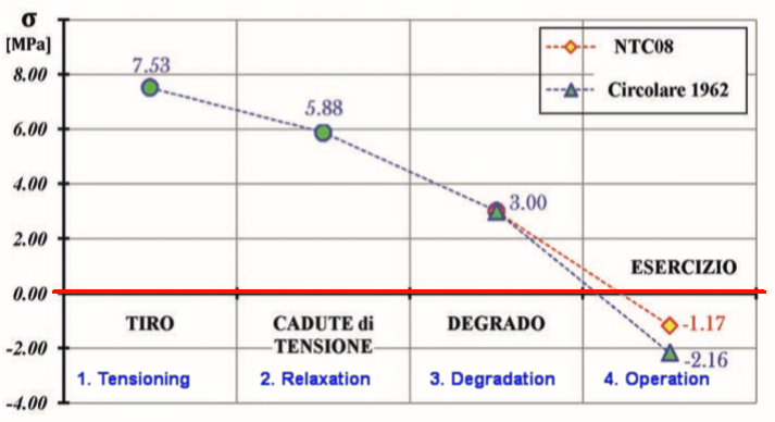
Image 6 (Sala 2016 - modified to include English translations): Longitudinal compression in the post-tensioned concrete stay beam of the similar Carpineto Viaduct. After initial tensioning in 1977, compression was set to 7.53 MPa (77 kg/cm²), but had decreased by more than half, to around 3 MPa, by 2013. Under heavy service loads, the longitudinal compression would fall below zero, resulting in rapid deterioration and putting structural stability at risk. - Because the steel cables are bonded to the surrounding concrete, small cracks in the concrete inevitably lead to corrosion and further deterioration.
- Because the cables cannot be inspected because they are embedded in concrete, corrosion and individual wire or strand failures cannot be detected.
In more modern designs, to enable continuous monitoring, cables can be electrically insulated so that individual wire failures can be detected by changes in the electrical resistance of the cable. - Neither can the current compression in the concrete be measured easily.
- Thus, both insufficient and excessive tension need to be avoided in the concrete stay beams. Therefore, a carefully defined range of post-tensioning forces had to be determined and applied during design and construction, with possible later recalibrations.
-
Because of steel relaxation and concrete creep, cable tension needs to be monitored at suitable intervals and, if necessary, recalibrated. Unfortunately, neither effective monitoring nor retensioning is possible in the Genoa design. The lack of precise, thorough and continuous monitoring options (corrosion, wire or strand failures, concrete compression) is not a favourable feature and may lead to unobserved critical deterioration.
Around 1993, pylon 11 received twelve additional external reinforcement cables to mitigate some of the above issues:
 |
| Image 7: Pylon 11 - External reinforcement cables installed 1992-1994 (Hasenjäger 2007) |
Several challenges arose:
One major problem was that the tension applied to these additional cables should not increase the total combined compression of the thin concrete beam. Applying additional compression would probably have damaged the thin concrete stay beam. The successfully applied solution can be summarized as extremely complex: it consisted of cutting a section of the old concrete stay beam, thereby also cutting the old cables inside, while subsequently increasing the tension in the new external cables.
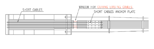 |
| Image 8 (Malerba 2010): Pylon 11 - anchorage of additional reinforcement cables; cutting of existing cables. |
Concluding postscript:
I examined a number of articles on the structural analysis and repair of Morandi-type bridges, written by different authors and by Riccardo Morandi himself.
Riccardo Morandi gave three main reasons for choosing concrete stay cables for the Polcevera Viaduct:
- To create a rigid bridge frame consisting of pylons (interlaced A-frames and V-shaped piers), stay cables and the bridge deck. This would also reduce vertical movement of the cantilever deck under variable traffic loads and therefore reduce torsion at its fixed end.
- To reduce stress in the inner A-cables
- To protect the steel cables against weathering and chemical attack
It is interesting to observe that most other authors give rather different explanations for why Morandi may have chosen this particular design. This divergence may indicate that there was not a substantial rational argument in favour of the concrete-encased stay design when considering its drawbacks.
It must be noted that the cable stays of the very similar Lake Maracaibo Bridge in Venezuela were not cast into a concrete beam.
 |
| Image 9 (Casado 1962): Maracaibo Bridge in Venezuela after completion in 1962. The bundled stay cables are not cast into concrete beams. |
 |
| Image 10 (Casado 1962): Maracaibo Bridge in Venezuela after completion in 1962. The bundled stay cables are not cast into concrete beams. |
This is even more interesting considering that the Maracaibo Bridge (1957-1961) was conceived five years before the Polcevera Viaduct (1962-1966).
Morandi must have decided around 1962 to abandon the simpler exposed steel-cable layout in favour of the more complex post-tensioned concrete stay-beam design.
by Kristian Hasenjäger
Last updated: December 15, 2021:
* Added image 5
* Changed from "A-type cables" to "A-type cable bundle" to make clearer that 12 (A) and 4 (B) independent cables respectively form one type-A/type-B bundle.
* Casting of post-tensioned stay beams was most likely not carried out using precast concrete boxes; text modified accordingly.
Bibliography
|
- Camomilla-Pisani-Martinez-Cabrera (1994) Repair of the stay cables of the Polcevera Viaduct in Genova
- Casado C (1962) Puente sobre el lago Maracaibo - Informes de la Construcci¢n Vol.15 n146
- Codacci Pisanelli (2001) The Bridge on the Wadi Kuf valley - Libya Rehabilitation and maintenance project
- Della Sala - Sabatello (2016) Viadotto strallato Carpineto I
- Hofacker H (1960) Die Maracaibobr?cke in Venezuela - Ausfuehrungsprojekt
- Malerba P.G. (2010) Managing Old Bridges - Bridge Maintenance, Safety - Management and Life-Cycle Optimization - Proceedings of the Fifth International IABMAS Conference - Philadelphi USA,11-15 July 2010
- Morandi R. (1969) SOME TYPES OF TIED BRIDGES IN PRESTRESSED CONCRETE
- Morandi R. (n.d.) Manuale di ingegneria civile Zanichelli-esac volume II
- Morandi R. (1968) Viaducto sobre el Polcevera en Genova Italia
- Morandi R. (1979) Durabilita-ponte
- Podolny W. (1977ca.) Construction and Design of Cable Stayed Bridges
| 3: Guest - 7.8 years ago | Aug 21, 2018, 8:13:18 AM |
| 2: System Admin - 7.8 years ago | Aug 19, 2018, 10:19:03 AM |
| 1: Guest - 7.8 years ago | Aug 18, 2018, 4:12:50 PM |